Building the M0NKA mcHF SDR transceiver
Back in March 2015 I was looking for a new electronics building project. I wanted something that would be a challenge but also be useful so a transceiver project seemed like a good idea. After considerable research I thought that an SDR based transceiver would be useful as this was something I had little experience of. I discovered the mcHF transceiver created by Chris, M0NKA.
Here are the features of the mcHF transceiver:
- Standalone and compact embedded transceiver
- Operates on USB, LSB, AM and CW
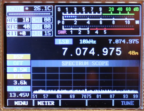
- Large 2.8 inch color LCD
- Four encoders and 17 buttons for easier operation
- Fast and fully electronic RX/TX switching
- Two USB ports – for PC control and external keyboard
- Two temperature compensated oscillators/clocks makes it ideal for digital modes
- Four digital filters – 1.8kHz, 2.6kHz, 3.6kHz and 10kHz
- Built in Iambic Keyer that supports Mode A and Mode B
- Large 48kHz spectrum display
I decided to purchase the PCBs and displays from Chris. At the time he wasn't offering kits so the only option was to order all of the other parts seperately. Luckilly we have an account with Farnell at work so I was able to buy almost all of the parts from there. Chris has since started offering a UI (user interface) board kit containing all of the parts needed to make this board. He is planning to offer an RF board kit at some point. This would be especially useful as some of the components (output transistors, toroids etc.) can be quite difficult to find.
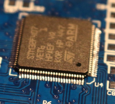 Once everything had arrived, I made a start. I decided to solder the most difficult component first, this is the STM32F407VET6 which is an LQFP-100 micro controller and effectively the brains of the mcHF. I decided to use the 'drag-soldering' technique which involves tacking pins on each corner and then dragging the soldering iron across the other pins and then using desoldering braid to remove any excess solder. I was initially concerned that I had slightly mis-aligned one row of pins but continuity tests and checking with a loupe showed that all was well.
Once the UI PCB was fully assembled, it was also necessary to assemble the PSU section of the RF PCB in order to test it so I did this and was quite surprised that the board was detected by the STM32 software and I was able to upload the mcHF bootloader and then use the provided mcHF uploader to send the latest version of the firmware to the board.
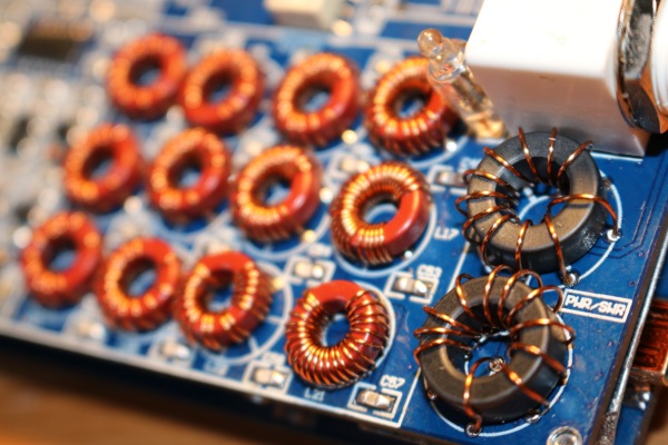
Once I had completed this, now was the time to build the rest of the RF board. There were a number of "specialist" components required that were not stocked at Farnell so I had to wait for these to arrive (mainly European eBay suppliers). There are a number of hand-wound inductors (BPF/VSWR bridge etc) that took a while to wind according to the specifications. I found a simple inductance meter invaluable for this.
There are also a fair number of modifications, with V1.4 of the PCBs (which I have) more of them are simple component substitution where more appropriate values have been discovered. There has been much discussion about power output being low on the higher bands and a number of alternative inductors have been suggested to improve this.
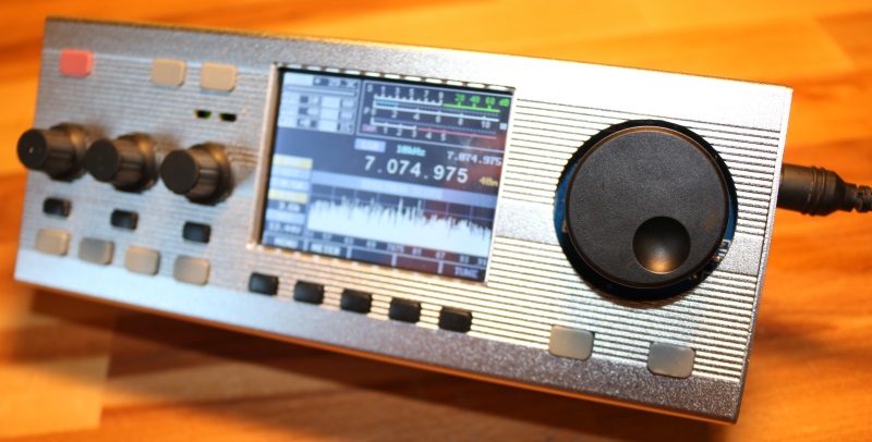
Here is my (nearly) completed mcHF:


Comments